Saturday, December 20, 2008
Assemble
Assemble HDA
new to 9.5 is the assemble HDA.
I first stumbled on this when i used a shelf tool to make a RBD Glue object. The Assemble HDA was automatically added just like the Auto Dopnet is added.
From the help file, Assemble is used in conjunction with Break and Shatter. Gone are the days of manually cutting up your model it seems ! The Break SOP already has bundled in it a fractalised grid or box or sphere - your choice, and boolean / Cookie operations that break the model up into seperate pieces for you !
Shatter goes one step further and allows multiple breaks by uisinfg the foreach SOP to re-iterate breaks over your object. I chose 10 breaks - and it bogged down quite a bit.
Once you have a bunch of 'shards' or pieces, you generally want to group these into their own groups with a common group prefix name, allowing you to use RBD fracture or RBD Glue DOPS to complete the sim.
This is where Assemble comes in. (Shatter already has an Assemble HDA bundled in it).
Assemble essentially uses a connectivity SOP and a partition
SOP to group all the pieces and give them a common prefix to the group names. It also has some options for edge cusping and faceting.
If the broken object is made Dynamic - Assemble is added automatically - as it did for me.
hers some more links:
http://forums.odforce.net/index.php?showtopic=8143
a shatter script for maya
Sunday, November 30, 2008
pompom test
my intial test for some cheerleaders pom poms
to make this i used wire dynamics, and fleshed it out with a trail sop.
my next version will have only 3 colours created with groups and wire to wire collisions and wire to handle collisions.
to make this i used wire dynamics, and fleshed it out with a trail sop.
my next version will have only 3 colours created with groups and wire to wire collisions and wire to handle collisions.
Wednesday, November 19, 2008
Tuesday, November 18, 2008
Remove Lonely Verts
this entry contains a little bit of VOP-SOP fun as well as outlining the
process of making a digital asset in Houdini.
my friend Rob Kelly initially nutted this out - then i found that i needed
it, so i set about making one for myself which turned out to be easier than i thought.
my first attept was in H8 and i remember getting frustrated with for loops not working as i expected - but now with H9's Vop Sop - a truly versatile SOP. {i have since removed my sheep joke from this entry :D }
the main application for finding lonely verts ( verts that have less than 3 neighbors )
is to delete them so they dont interupt the subdivision process
Lonlely verts are often left behind in the modeling process - whenever several connecting edges are dissolved.
I added a VOP SOP - then after mucking around with the for each VOP - i realised every op in the VOP SOP was going to be applied to every point in the incoming geometry anyway - so i didnt need a for loop at all.
in the VOP SOP i simply have the point number from the global parameters (fom the incoming geometry) going into a neighbor sop - which counts how many neighboring points the current point has - and then decides if it should be coloured or not.
The trick here is to get the neighbor count to either zero or one which will act like a switch.
i noticed that a lonely vert has only 2 edges coming out of it - where as a 'healthy' vert has usually four - or three depending where it is on the model. There are exceptions however ! ie - the corners of a grid also only have two neighbors !
The only way ive though of so far to deal with these is to explicity ignore them by putting them into a group, before the asset does its job. We can streamline this process a little by some sort of edge detection or at the very least providing a field with the group name to ignore, as part of the asset.
The coloured points are grouped by their colour and the option is there in the asset to delete them or not. Having a toggle is a good way to see what the bleep is happening.
Wednesday, November 5, 2008
Saturday, November 1, 2008
monthly research : IFD files
the IFD (Image File Descriptor ?) files in Houdini / mantra are the equivalent of the RIB files for Renderman -
they are a description of the 3D scene for that frame.
from the help files:
ifd is the file format produced by houdini..and consumed by mantra.
The IFD file contains a complete description of the scene and how to render it.
you can render an image directly from an ifd file in the shell without opening houdini simply type:
mantra < [the name of the ifd file]
I wonder what an ifd looks like if i open it ?
heres one i made from houdini:
IFD created by Houdini Version: 9.5.255
# Generation Time: Nov 05, 2008 at 14:14:24
# Render Defs: /lv0/opt/hfs9.5.255_linux_x86_64/houdini/soho/IFDmantra9.5.py
# HIP File: /lv0/tbe/shots/6_4/hip/6_4_ink_wire_tweak_v08_t02_dp.hip, $T=16.44, $FPS$
...and the rest is garbled by my text editor - pico.
they are a description of the 3D scene for that frame.
from the help files:
ifd is the file format produced by houdini..and consumed by mantra.
The IFD file contains a complete description of the scene and how to render it.
you can render an image directly from an ifd file in the shell without opening houdini simply type:
mantra < [the name of the ifd file]
I wonder what an ifd looks like if i open it ?
heres one i made from houdini:
IFD created by Houdini Version: 9.5.255
# Generation Time: Nov 05, 2008 at 14:14:24
# Render Defs: /lv0/opt/hfs9.5.255_linux_x86_64/houdini/soho/IFDmantra9.5.py
# HIP File: /lv0/tbe/shots/6_4/hip/6_4_ink_wire_tweak_v08_t02_dp.hip, $T=16.44, $FPS$
# Output driver: /out/ink_wire_BG1
ray_version VEX9.5.255
setenv HIP = "/lv0/tbe/shots/6_4/hip"
ray_property object velocityscale 0.02
# Retained geometry
# SOP /obj/rs_holdout_map1/geo1/RENDER
# Save geometry for /obj/rs_holdout_map1/geo1/RENDER at time 16.44
ray_start geo # {
ray_detail /obj/rs_holdout_map1/geo1/RENDER stdin
BgeoV^@^@^@^E
...and the rest is garbled by my text editor - pico.
Friday, October 10, 2008
soft body test with particles
Tuesday, September 2, 2008
Copy Stamp Play
some copy stamping.
the scale and rotation (mostly in Y) is randomized based on $PT.
I used the fit01 expression to fit my random values into a desirable range.
in the first pic, the cards are just planes, but in the second, the cards are 3D with a slight bevel, and some noise (offset for each card through stamping)
to get the Houdini logo - i made sure 'use Template Attributes was on.'
so the Cd att. (color) was copied from the grid (the template) to the cards.
In my shader - i told it to use a Cd parameter and wired this into the colour so the colour info was piped through to the shader as well.
In my current version - i decided to animate the swirl feature of the logo into appearance. In the top view i made a rough poly curve /line that matched the spiral using my grid (with the texture's colours transferred to its points)
as a template.
I then gave it white point colours and animated a sphere along it, then transferred the color to the cards. For the sphere to leave a permanent trail behind it I used a trail sop....thus the cards are animated to turn white.
One issue i had with this attribute transfer - was that because the sphere with the white points is animated - and the grid/ ground plane is of finite resolution - the distance from the spheres points and the grids points changes as the sphere moves around - giving a flickering effect on the white. - The attribute transfer's distance is constantly changing as the spheres points move closer to and further away from the points on the grid.
To get around this - Rob suggested using a group. This was n easy solution - the sphere with trails - intersects the points on the grid (or the points scattered on the grid) and adds them to the group. This group then controls which points have their point colours changed.
Wednesday, July 30, 2008
Tuesday, June 24, 2008
weekly.....monthly research...
a glance at nuke...
i had a bit of a play with Nuke this morning...so i though why not have another
look at it...
from wikipedia:
Nuke (the name deriving from 'new compositor')[1] was originally developed by Bill Spitzak of Digital Domain for in-house use beginning in 1993. Nuke used the FLTK toolkit, which was developed in-house at Digital Domain and was subsequently released under the GNU LGPL in 1998.
In 2007, The Foundry, a London-based plug-in development house, took over development and marketing of Nuke from D2.[7] The Foundry released Nuke 4.7 in June 2007,[8] and Nuke 5 was released in early 2008, which replaced the interface with Qt and added Python scripting, and support for a stereoscopic workflow. Nuke supports use of The Foundry plug-ins via its support for the OpenFX standard.
--------------------------
some notes:
just like fusion, you can hit 1 to get a viewer to pop up to display the node your focussed on.....which means you can select any node and then hit one to pop up a
preview of your tree at that position.
I noticed the menu has an open recent option....with the hot keys Alt - Shift -1, 2,3 etc...
Alt-G go directly to a frame...cool !
Alt-I script info..
Search / - just like houdini and linux !
CTRL-D disconnect or remove input
Zoom:
CTRL and a number to zoom in
ALT- and a number to zoom out.
F for fit and + and - to zoom in and out.
ALT-MMB for interactive zoom
ALT-LMB for Pan
` toggle the viewer
SHIFT ~ curve editor
S settings - you can specify a proxy here as well as general project settings
Shift - S preferences...
------------------------------------
ok from here i decided to investigate based on common tools:
a more structured approach...
splines / curves
add a bezier node under the draw submenu of 'modifiers' or tools
or just press P
CTRL-ALT-click to draw....
it seems by default the spline is closed.
some thoughts / questions and answers about splines from working in Fusion , After FX and Shake:
P (shift-p) allows me to draw a path
can i easily hide them ? -
O for Overlay toggles all the viewer type overlaid controls
can i animate the number of CV's ? and how is this interpolated ?
O for Overlay toggles all the viewer type overlaid controls
can i animate the number of CV's ? and how is this interpolated ?
would I really want to do this ? i noticed shake was kinda klunkyu in this area -
you had to plan ahead with your keyframes.
can i easily control a feathered falloff or soft edge of the spline ?
using control gives me a soft edge for the bezier - indicated by a dotted line
you had to plan ahead with your keyframes.
can i easily control a feathered falloff or soft edge of the spline ?
using control gives me a soft edge for the bezier - indicated by a dotted line
the dotted line seems to actually indicate the beginning of the fall-off - not the end.
The solid line indicates the end of the fall off - where the spline is not having any effect - the outer most extreme region of the spline.
in fact moving the dotted - inner line can actually move the outer line as well - as if they were linked. CTRL gives independent control.
like shake.
x or right clicking and choosing 'BREAK' on the point will break the bezier handles.
cusp (corner) and blur / unblur and smooth (relink bezier handles) is also avail from this RC menu.
the help button has quite a few tips:
there is a transform jack when a few points are selected
you can also select points by clicking on the line between the points
Can i easily animate the spline as a whole ?
(there appears to be a handle like in shake)
the actual function of splines and masking seems a bit different
you can have a bezier node function with no input - it can exist in it s own right
in order to get some results that were logical to me...
i had to :
to be continued....
ok so i had some difficulties getting used to the masking with Nuke.
finally i read some of the help files: :)
from the first tutorial script i see that adding a mask or bezier shape to an image
fills it with white by default - so by changing the colour to black and inverting the mask i was able to cut a section of the im age out and overlay it (over) on something else.
So if want to use a filtere to affect just a region of an image this is one way i could do it.
Im really after a more direct way - luch as in fusion where you apply the filter to an image (which applies it to the entire image) then you can plug a mask into an imput designed for accepting masks and the filster is constrained tot hat mask.
the same process is complete in three nodes rather than four..
Monday, June 16, 2008
mercedes glk website launched !
Mercedes Job makes it to SideFX's REEL !!!
www.mercedes-glk.com
looks amazing...but be warned - it takes a while to come down
hats off in a big way to the talent at Realise and Kanuka Studios !
www.mercedes-glk.com
looks amazing...but be warned - it takes a while to come down
hats off in a big way to the talent at Realise and Kanuka Studios !
Sunday, June 1, 2008
ICP, Isixpack, BIC (rangi sutton)
ICP - convert images to rat format for better memory usage in Houdini.
after typing in a shell (in a houdini environment)
i get:
icp copies one image file to another, optionally performing simple
operations.
icp [options]
some options
-u output uncompressed if supported
-v turn on verbose
-f flip vertically
-F flip horizontally
-R flop image 90 degrees couter clock wise
-r scale to w x h res.
-s scale to a percent of the original
-c crop area in UV coords
-C crop area in pixels
-P include planes at the specified indices
-Lload with cineon LUT
-Osave with cineon lut
-N do not convert cineon from 10 bit log
isixpack takes 6 images and makes a reflection map in rat format.
type for help
after typing in a shell (in a houdini environment)
i get:
icp copies one image file to another, optionally performing simple
operations.
icp [options]
some options
-u output uncompressed if supported
-v turn on verbose
-f flip vertically
-F flip horizontally
-R flop image 90 degrees couter clock wise
-r
-s
-c
-C
-P
-L
-O
-N do not convert cineon from 10 bit log
isixpack takes 6 images and makes a reflection map in rat format.
type for help
% isixpack -
------------------------
from the help - there is 3 ways to convert images.
1. through COPS
2. converting in MPLAY
3. isixpack - mentioned above
AH HA !
what i was really after was the bic command (written by rangi Sutton)
the bic command converts images between formats.
Usage: bic -i-o [-e] image_file_names
Takes each of the image files specified with image_file_names and converts them
to image files of the format specified with the output_format. The files
specified with image_file_names should be image files of the type specified
with the -i input_format.
Valid file formats are:
pic jpg jpeg tga gif gif89 rgb sgi yuv pict pix cin tx rat exr
Input files should have these suffixes. eg myrender.rgb
Requires a valid Sidefx Houdini License.
Written by Rangi Sutton on 20/3/97 for HM3d Graphics Systems
Monday, May 19, 2008
Ball o' Worms
Trials and tribulations...
well..im working on a new ball of worms and theres been some interesting developments...
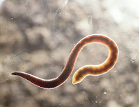
the worms...
i took the old geometry from max in obj format and decided i could improve in it in Houdini - the ends of the worms in max had some 'bogeys' due to bezier handles being present and the fact that i told max to create the geometry in the spline object itself.
in Houdini, i used partition and connectivity to create a group for each worm, then i deleted all the worms except one, then rebuilt the group with a copy SOP - an awesome technique first shown to me by one of David Gary's old video tuts - the particles flowing along the l-system.
this way - all operations applied to the one remaing worm can also be applied to the entire list of groups / of worms :)
i grouped a bunch of co-linear - in worm space :) - points by using group by range, and then made a new spline from this, then swept new worms after re-sampling the spline giving me much cleaner worms...the obj was much too high in res.
then i decided to add a ring slightly fatter around the middle - see the pic ? and this was done by extruding - which was not good for the UVs - likewise i capped the open ends of the polys - bad for proceduralism and UVs. There was also a UV errorof some sort ruining my renders.
so today i went about solving these issues and opened up a can of well.....worms :|
my proc method of selecting the ends had to be scrapped - i made groups for the first and last point of the splines the swept the worms - proc ok - but then after copying spheres to these points i wasnt really cleanly selecting points or prims for extrusions or capping.
the sweeping itself also had to be redone unfortunately - as did the UV mapping - but uncovered some interesting techniques. The UVs were made with Rob K's (meshsmooth) unfold curve SOP
which looks at the angle of segments on the curve and then applies that same angle as a rotation to the specific segments and thus straightens out the curve. With the same method used for the backbone curve - a sweep with give you a flat plane which can easily be mapped - these UVs can then be transferred to the same sweep (with curly cuves) thus mapping the worm.
I also decided to go to town with the image and add some rain and all the water FX that would go with it - rain splashing against the ball of dirt and trhe worms and causing mud, and water dripping off the worms and bouncing around on the set / cyclorama. Joy...more cans of worms !
closest render I have to the original houdini render:
Tuesday, May 13, 2008
some Renderman
I can translate this to VEX later.
seems i need to know vi or something similar for efficient text editing.
at the moment i have Context which seems ok and has custom features for editing RIB files but not sure about VEX.
from "Renderman for beginners"
1.4 "How a renderer works"
3D scene description
|
object to world to camera transformation
|
clipping, culling, projection
|
raterisation,hidden surface elimination, shading
|
rendered image in frame buffer or stored on disk.
2.3 "How PRMan works" & Reyes algorithm
Rib file is parsed (scanned)
Primitives' bounds are checked to see if
they lie in the cameras frustrum ('vision') -
if not those 3primitives no longer need any calculations
|
primitives are checked to see if they are small enough for dicing
and if not - broken down or diced themselves into smaller chunks / sections
until they are small enough for the Reyes dicing
|
Reyes dicing into micropolygon grids
each primitive that is small enough is diced into a grid of micro-polygons
It is these micropolys that get shaded and eventually contribute to the
final pixel colors
|
shade at grid verts
|
bust the grid into individual micropolygons
|
each micropolygon is tested for bounds
incase a displacement shader has moved the position of the micropoly
|
each micropoly is then sampled at pre-determined sub-pixel locations
(There number of sub-pixel locations is set up as a control in the RIB file
or in the interface in the case of Mantra)
and a 'visible point list' is made with the Z depth values
|
the point list is then spatially blended and collapsed into a final pixel colour and opacity using filtering to weight between several samples for that pixel.
Some filtering algorithms you may have seen are:
Catmul-Rom
Linear
Blackmann
Hanning
etc
|
Finally - the array of pixels is sent to a display buffer or saved to disk.
Tuesday, April 22, 2008
ocean shader
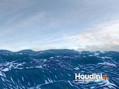
heres a crack at an ocean scene,
not happy with it yet...but its been interesting.
ill have to find a model to stick in the water...
i got a SSS pass in there but its hard to tell if it really working properly.
no white caps yet and no tru Zdepth yet - my dodgey ZDepth was made by using an edge detect on the alpha of the water essentially creating a horizon line then blurring this and adding it to itself for the desired effect.
this was used as a mask for desaturation and SSS as well as blur.
the spec is bloomed out as well...all comped in Houdini :)
edit: next time i might try and reduce the wave height in relation to zDepth to try and
fake the scale of the scene - like a perspective cheat...any ol' trick to reduce rendering times on my old box.
edit: looking at other peoples work - i realised
i can fake the distance with a flatten effect based on camera distance.
-----------------------
some more shader practice:
simple opacity
dont forget:
the RGB has to be multipled by the Alpha to get some black for the OPACITY.
in this example i had a 32 bit TGA - which i then broke into its RGB vector and a 4th float value (the alpha) with a convert VOP
(convert Vector4 to Vector)
an image with an alpha channel may need the 'premultiplied' treatment.
- this can be done in COPS.
Monday, April 21, 2008
weekly research: MIP mapping
what is MIP ?
wikipedia has the answers
Mip maps (invented by Lance Williams in 1983)
... are pre-calculated, optimised collections of bitmaps that accompany a main texture, intending on increasing rendering spped and reducing artifacts.
MIP is an acronym, from the latin : multum in parvo, or "much in a small space"
If the full res map isnt required - the renderer will automatically switch to a lower res version, or interpolate between the full- res version and a lower res version - if tri-linear filtering is enabled.
see anistropic mip mapping.
capsule asset re-made
the original capsule asset post (post #2 is updated with some pics)
and the asset was remade.
original capsule post
and the asset was remade.
original capsule post
Wednesday, April 16, 2008
crab update !
HOOOPLA !
a new render of the crab with rangi's HDRI shader
there'll be more renders as his face design will be changing...
Tuesday, April 15, 2008
Saturday, April 12, 2008
ball ' o worms
Wednesday, April 9, 2008
LINUX file permissions
from www.linuxforums.org/security/file_permissions.html
r readable
w writable
x executable
u user
g group - ie Administrators
0 others - not a member of a group or the owner of the file
a all
- no permission
use ls -l to see file permissions
eg
ls -l myfile
-rwxr-x--- 1 george administrators 10 2006-03-09 21:31 myfile
so for george - the owner - the file is readable , writable and executable.
for other administrators - the file is only readable - not writable but still executable
other users cannot read, write or run this file.
changing permissions : chmod
if george wanted to give write permission tot he other administrators
he would type
chmod g+w myfile
see the url for details
tricks from the forums ! - thx to all Houdniks out there !
Tuesday, April 8, 2008
some HScript ! arc, argc
arg - looks really useful.
returns an argument - the one4 specified from a list of argts in a string
it fillows the format arg("stringline", float arg number - starting from 0)
ie
arg("yellow world ",1) returns world
arg("yellow world ",0) returns yellow
argc (arg-count) returns a number of arguments
eg
argc ("This string has eight words seperated by spaces") returns 8
argc ("Quoting `makes this one arg`") only returns 2 as `makes one arg` is only counted as one arg - because of the quotes.
Monday, April 7, 2008
weekly research ! some MATHS
Summation
reading some research on making car shaders i saw some crazy maths i recognised from high school so i was curious as to what it all meant.
from wikipedia
Summation is the addition of a set of numbers; the result is their sum or total.
Vetcors
unlike scalars, vectors have more than one component.
they have a direction and a magnitude.
they can be notated with an arrow over the start point and the end point
there are a few methods for addition
a. the end to end method - move one vector to the end of the other one
b. parrallelogram method
in addition they are associative A+B = B + A
negative vectors (5:31)
Subtraction of vectors
A - B = C
A+(-B) = C
(the negative of a vector is pointing in the opposite direction)
when you add scalrs - there is only one answer
but with vectors there could be more than one answer if there is missing information
ie we dont know the direction of a vector - but we kow its magnitude.
with a 3D say vector A vector - we project it onto the xyz axes
the unit vector is like a control
the axes are always pointing in the positive direction
and the magnitiude is always 1 for each axis.
it is noted with little roofs on the vectors to show its a unit vector
decomposition of the vector A:
we break it down into its 3 components
the magnitude is the root of A2 + Y2 + Z2
it is notated with Abs lines / vertical bars around the A (magnitude is a scalar)
Multiplication
there are two methods
dot product / saclar product - notated with a fat dot
the angle method
we project B onto A - then the dot product is |A| |B| cos Theta
the dot product can be pos or neg or = to zero.
it doesnt matter if you take the acute angle of theta or the obtuse angle of theta
their cosines are the same
to be continued !
Tuesday, April 1, 2008
weekly research: CHROMATIC ABERRATION
from wikipedia:
chromatic aberration occurs when a lens has a slightly different refractive index for different wavelengths of light - resulting in some fringing of some colours.
...just like 'The Dark Side of the Moon' - :D
this could be and is often used to enhance realism in cg images.
how ?
here's my hack
we could render split the RGB and adjust the hue and offset or distort the channel a little then mix it back in the comp.
& here' s my attempt at a copnet - made long after this post : 22 Jan 2010 !
and here's a beautiful example from Andrew Schneider:
schneiderFX/Macro
UPDATE...
I've applied it a little here for my bubble render...hopefully it helps sell it a bit !
UPDATE #2
I stumbled across a link to a great tutorial for achieving the effect in After FX
a couple of points I got from it:
the colors used in the effect in this tut were pure Cyan and Magenta
The other thing was that the effect was used more toward the boundary of the image - the effect was masked off in the center of the image with a soft-falloff / a large amount of feathering.
Friday, March 28, 2008
weekly research : DOF
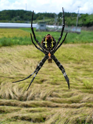
spider from Nakamura, Japan. 2007.
the spider is more in focus than the road or background foliage
Im no photographer - but i think the focal point was somewhere in between the spider and the camera - as the spider is non as sharp as it could be.
in Houdini : try lowering your F-Stop to increase Blur for DOF effects
eg:
addendum:
from Side Effects website:
hscript expression for distance from cam to null)
vlength(vtorigin("/obj/path_to_camera", "/obj/path_to_null"))
from exhelp:
vector vorigin (string obj1, string obj2)
Returns a vector of a objects's transforms.
This function will return a vector with 6 values in it. The values are
set to "[TX, TY, TZ, RX, RY, RZ]" for the position of obj1 relative to
obj2.
This can also be thought of as the position of obj2 relative to obj1.
If the empty string ("") is specified for either obj1 or obj2, then
the identity transform will be used instead. For example, if obj1 is
the empty string, then the world space position of obj2 is returned.
vtorigin (string obj1, string obj2)
Returns a vector of an object's translations.
This function will return a vector containing the translates required
to transform obj1 to the space of obj2.
This can also be thought of as the position of obj2 relative to obj1.
If the empty string ("") is specified for either obj1 or obj2, then
the identity transform will be used instead. For example, if obj1 is
the empty string, then the world space position of obj2 is returned.
RELATED
origin
vorigin
vrorigin
originoffset
in my efforts to learn more about the world of digital fx - i thought id try and document some stuff weekly.
tonight some DOF
links
luminous-landscape.com
online DOF calculator
Retouchpro.com
Wikipedia
Large Format Photography
what do i already know ?
- it greatly enhances realism in cg.
- it can be slow to calculate in cg- it definitely has been slow to calculate so far in my experience with 3DSmax (3D DOF ?) .
- there are cheats - blurring with z-depth has been my solution for most my personal work so far.
- it has a range. the distance from the subject to the camera and the camera lens settings determines if the subject falls within the focal range. if it is outside of the focal range - it will be blurry.
CoC - circle of confusion
the circle of confusion is is the diameter of a 'sufficiently small' blurspot.
A photograph is perceived as acceptably sharp when the blur spot is smaller than the acceptable circle of confusion. The size of the “acceptable” circle of confusion for the original image (eg film) depends on three factors:
- Visual acuity - quality of individuals eyesight - may be impaired by environment.
- The distance at which the final image is viewed.
- The enlargement of the final image from the original image.
it also figures that for DOF the typical magnification of enlargement from neg to print is 5x
so 1/6th of a mm div by 5 for the neg is .0333' mm - this is the "Circle of Confusion" that many 35 mm lens manufactures use when making their lenses. it is a circular shape because of the nature of the lens.
a definition of DOF
"The area in front of and behind a focussed subject which stays sharp in the photographic print."
this should be "The area in front of and behind a focussed subject which stays sharp in the photographic print - within the limits of the applied COF."
DOF is also the far focal point distance minus the near focal point distance.
one of the laws of optics seen in DOF tables is that the DOF extends one third in front of the subject and 2 thirds behind it. This means there is twice as much DOF behind a subject as there is in front of it.
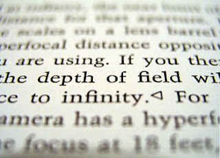
the Hyperfocal Distance
the hyperfocal distance is the nearest DOF distance at which the DOF can extend to infinity.
focussing the camera at the hyperfocal distance enables the largest possible DOF for a given f-number. Focussing beyond the hyperfocal distance will not increase the DOF but actually decrease it or 'waste it' as some photographers say. The far focal point is staying the same - at infinity - but the near focal point is moving further away - so the focal distance is getting smaller.
from wikipedia:
although a lens can only focus on one point - the falloff of focus is gradual on either side of the focal point.
What is the science behind it ?
from : www.dofmaster.com/equations.html
- hyperfocal distance
f is the lens focal length in mm - everything should be in mm
f^2 is f squared
N is the f number
c is the circle of confusion in mm again.
to convert the H to feet from mm : divide by 304.8 and 1000 for m.
- near distance of acceptable sharpness
- far distance of acceptable sharpness
s = focal distance
see wikipedia's formulae for more detail
next week aberrations !
Subscribe to:
Posts (Atom)